Creo
Overview
Creo is a software suite which is developed by Parametric Technology Corporation (PTC) for supporting product design. Formerly Creo is known as Pro/ENGINEER.
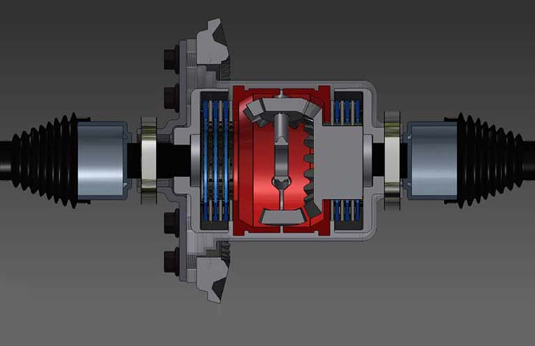
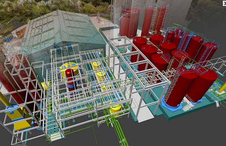
Creo is a CAD/CAM/CAE featured 3D solid modeling software. It is used by mechanical engineers/designers for solid modeling, assembly modeling, finite element analysis, 2D orthographic viewing, sub-divisional and NURBS surfacing, direct and parametric modeling, and NC and tooling functionality.
Creo Elements/Parametric competes with other software like Solidworks, CATIA, and NX/Solid Edge.
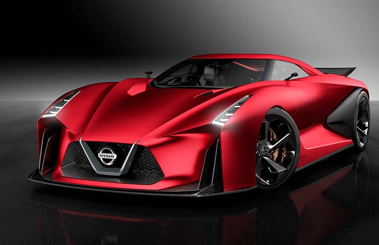
Creo parametric is an upgraded version of Pro-E software which is useful for modeling, analysis and simulation. It is broadly used for product design & development in various automobile firms and manufacturing plants.


Why to learn?
Creo helps everyone to utilize various parametric features such as 3D CAD solid modeling, 2D orthographic views, 3D direct modeling, schematic design, Finite Element Analysis and simulation, technological illustrations, and viewing and visualization.
By using this software designers/engineers can do product simulation, 3D mechanical design, analysis & testing, tool creation, design communication, and manufacture application.
User can easily go for seamless parametric and direct modeling product design as per their needs.
Learning Objectives:
CADD Center will help you to ace the associated features of Creo:
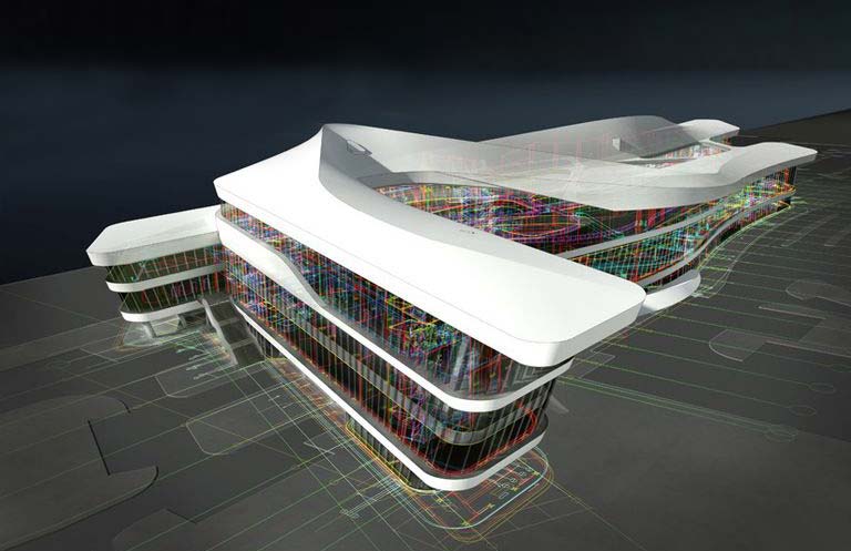
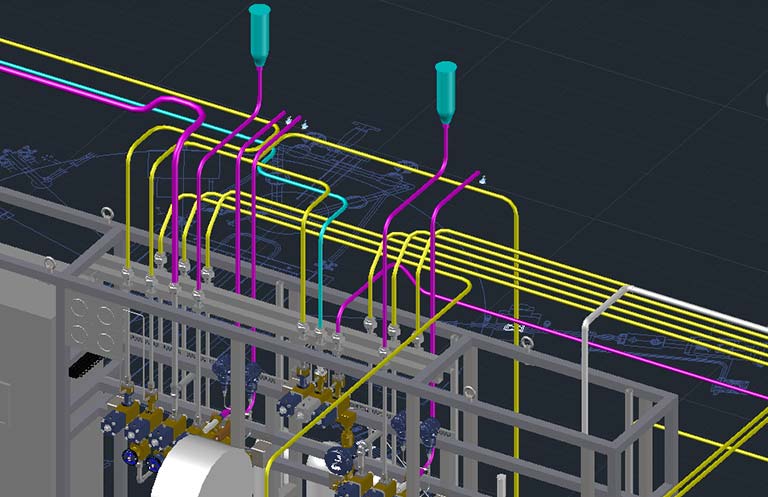
- Product Design: Using Creo Elements/Pro, designer will be able to generate complete digital representation of any product designs. Also, using this tool designer will be able to integrate other design disciplines like industrial & standard pipe work and further collaborative development.
- Analysis: Creo Elements/Pro covers thermal, dynamic, static and fatigue finite constituent analysis along with other designing tools to for the development of any product. These tool also includes human factors, manufacturing tolerance, mould flow and design optimization.
- Surface Modeling: Creo provides good surface modeling capabilities, using commands like Boundary blend and Sweep designer can easily create surface models. It also helps designer to create more capabilities to designer by providing advance options like Style (Interactive Surface Design Extension - ISDX) and Freestyle for creating complex models with ease.
- Manufacturing: With regards to single data source principle, designer gets rich set of manufacturing environment tools for tool designing and simulated CNC machining and output.
Learning Outcome:
- Student will have seamless data sharing ability; they can easily design entire process, from concept design work to manufacturing the final product.
- Student will have the ease of late stage change accommodation.
- Student can automatically do associative manufacturing and service deliverables generation.
- Student will be able to add references to sketches.
- Student can add manufacturing businesses transition into model-based enterprises.
- Student will have enough skills to increase productivity, do better concept design, increase engineering & manufacturing capabilities, do better simulation and additive manufacturing.